To explore large-er aspect ratio wings; one fine morning, I just thought it would be fun to put a truss-braced wing in a Piaggio P.180 "Avanti". The modified design CAD files are is available here. A comparison is shown in Fig. 1. I am too lazy to make 2 separate airplanes so I modified half of it so I can run a CFD analysis using one model and one mesh 🤣. A slight modification about which I will write later is the positioning of the flaps and ailerons. These are moved to the truss part from the main wing in the original design. The aspect ratio is of the truss-braced section is double the original. With a foldable wing, storage shouldn't be a problem?
Fig. 1, Row 1, L-R Top, bottom; Row 2, L-R front, back; Row 3 L-R, left, right views
Cruise conditions are taken from [1] i.e. ~12,500 m and ~163.6 m/s. The CFD mesh has 4,892,425 cells out of those, 449,732 are the the surface of the jet. I compare lift/drag of both halves. The modified section produces 36.15% more drag (force) as compared to the original design. The modified section however, produces 49% more lift (force) than the original design. L/D for truss-winged section is at 6.72 as compared to 6.14 for the original design. In terms of L/D, the truss-braced wing section produced 🥁 ... 9.45% more Lift/Drag. A resounding success 😁, I'd say. For validation of CFD, read this and this.
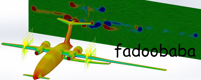
Some post processing I did, is shown in Fig. 2. Velocity iso-lines with vectors are shown around the wings. Vorticity is shown in the wake of the jet(s). Tip vortex is smaller and less intense behind the truss-braced wing portion but there is another vortex where the truss meets with the main wing. In the main wing, for the trussed-braced portion; on the pressure side; the high pressure zones extend for a longer portion of the span in the span-wise direction as compared to the original design. Same is true for low pressure zones on the suction side of the main wing. Some day I will write a nice little paper and sent it to an AIAA conference, till then 𝌗.
Fig. 2, Colorful Fluid Dynamics 🌈
Stream-wise vorticity is shown in Fig. 3. It is clear from Fig. 3 that the vorticity is less intense on the side with truss-braced wing as compared to the original design. Fig. 3 is colored by stream-wise velocity. The aircraft appears blue due to no slip condition.
Fig. 3, Some more Colorful Fluid Dynamics (CFD) 🌈
Thank you for reading, if you would like to hire me as your master's / PhD student / post-doc / collaborate on research projects, please reach out! 😌
References
[1] "Operations Planning Guide". Business & Commercial Aviation. Aviation Week. May 2016. [https://web.archive.org/web/20160815060134/http://www.sellajet.com/adpages/BCA-2016.pdf]


