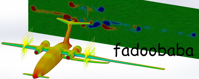
To explore large-er aspect ratio wings; one fine morning, I just thought it would be fun to put a truss-braced wing in a Piaggio P.180 "Avanti". The modified design CAD files are is available here. A comparison is shown in Fig. 1. I am too lazy to make 2 separate airplanes so I modified half of it so I can run a CFD analysis using one model and one mesh 🤣. A slight modification about which I will write later is the positioning of the flaps and ailerons. These are moved to the truss part from the main wing in the original design. The aspect ratio is of the truss-braced section is double the original. With a foldable wing, storage shouldn't be a problem?
I write about Propulsion, Aerodynamics and Renewable Energy (Wind/Hydro Turbines).
Monday, 17 April 2023
Executive transport aircraft with truss-braced wing (World's First)
Monday, 18 July 2022
High Lift Common Research Model (CRM-HL) CFD Simulation (with validation from Stanford CTR and NASA) Update 01: Formation Flight
This post is about the CFD analysis of the nominal (2A) configuration of the Boeing / NASA CRM-HL with flap and slat angles at 40 and 37 degrees. The configuration is shown in Fig. 1.
The dimensions are mentioned in [1] and is available here and here. The numerical simulations are validated with published literature [3, 4]. SolidWorks Flow Simulation Premium software is employed for the CFD simulations. The flight conditions are Mach 0.2 at 289.444 K and 170093.66 Pa [2].
Fig. 2 shows the computational mesh along with the computational domain. The surface mesh is also shown with Fig. 2. It can be seen that the mesh is refined in the areas of interests and in the wake of the aircraft to properly capture the relevant flow features. The Cartesian mesh with immersed boundary method, cut-cell approach and octree refinement is used for creating the mesh. The mesh has 6.5 million cells, of which around 0.71 millions cells are at boundary of the aircraft.
The simulations employ κ-ε turbulence model with damping functions and two-scales wall functions. SIMPLE-R (modified) as the numerical algorithm. Second order upwind and central approximations as the spatial discretization schemes for the convective fluxes and diffusive terms. The software solves the Favre-averaged Navier-Stokes equations to predict turbulent flow. The simulations are performed to predict three-dimensional steady-state flow over the aircraft
Angle of attack of 7 and 17 degrees are considered. At 7 degree angle of attack, the drag life and moment coefficients are within 6, 8 and 12% of the published data, respectively. For 17 degree angle of attack, the coefficients are within 4, 7, 33% of the published data [3, 4]. On average, the results of the present simulations are within 6% of the published data for force coefficients and within 12% in terms of pitching moment coefficient. The pitching moment coefficient will improve with refinement of the mesh, as shown by [3]; which I will do if ever I convert this into a manuscript 😂. The post processing from CFD simulations is shown in Fig. 3-4. Within Fig. 3, the iso-surfaces represent vorticity in the direction of flow, colored by pressure. The direction of flow is shown by black arrows. Streamlines colored by vorticity are also visible. It can be seen from Fig. 2 that the simulation captures important flow features such as vortex formation very accurately, in such small number of mesh cells. Fig. 4 shows wing of the velocity iso-surfaces colored by vorticity in the direction of flow, focused around the wing.
The simulations are solved using 10 of 12 threads of a 4.0 GHz CPU with 32 GB of total system memory of which almost 30 GB remains in use while the simulations are in progress. To solve each angle of attack, 3 hours and 47 minutes are required.
Update 01
References
[1] Doug Lacy and Adam M. Clark, "Definition of Initial Landing and Takeoff Reference Configurations for the High Lift Common Research Model (CRM-HL)", AIAA Aviation Forum, AIAA 2020-2771, 2020 10.2514/6.2020-2771
[2] 4th AIAA CFD High Lift Prediction Workshop Official Test Cases, https://hiliftpw.larc.nasa.gov/Workshop4/OfficialTestCases-HiLiftPW-4-2021_v15.pdf
[3] K. Goc, S., T. Bose and P. Moin, "Large-eddy simulation of the NASA high-lift common research model", Center for Turbulence Research, Stanford University, Annual Research Briefs 2021
[4] 4TH High Lift Workshop Results, ADS, https://new.aerodynamic-solutions.com/news/18


